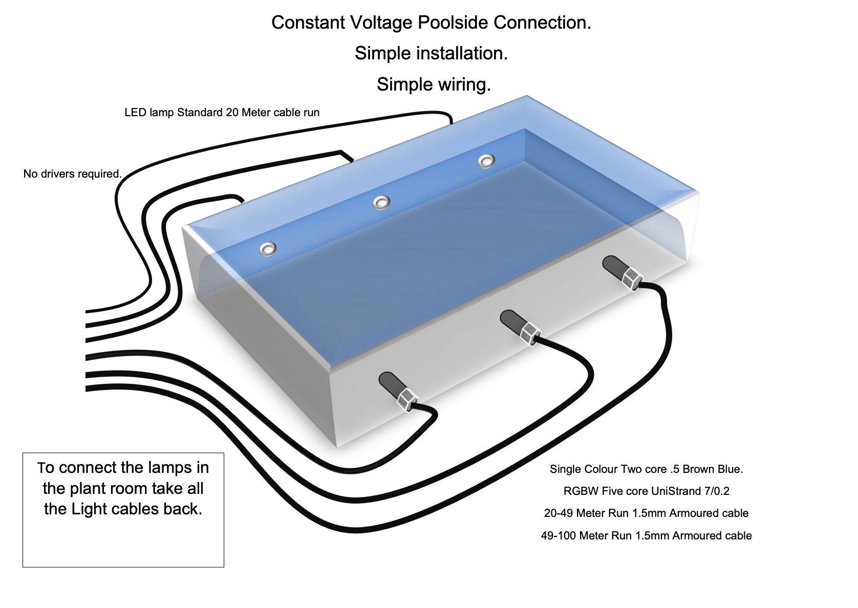
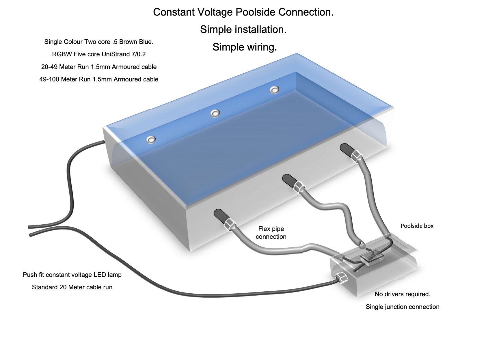
Constant Voltage Underwater LED light
Removable LED
No Need For Drivers
High Powered
Full 316 Stainless Steel
Waterproof IP68
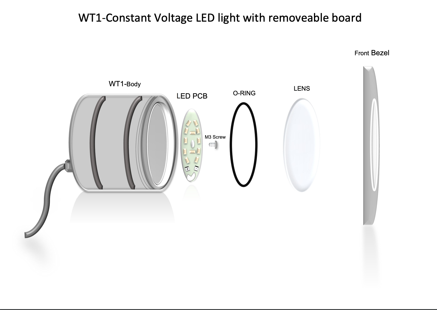
WT1-UWL
| CCT (K) | (5700K Cool White) (3000K Warm White) |
|---|---|
| CRI (Colour Rendering Index) | 85 |
| White Lumens | (900lm Cool) (750lm Warm) |
| White Wattage | 6W |
| Static Colour | Red 400lm Green 550lm Blue 350lm |
| RGB Wattage | 9W-3W per colour |
| RGB Lumens | Green 172lm Red 137lm Blue 162 Total 471lm |
| RGBW Lumens | Green 172lm Red 137lm Blue 162 Total 471lm White 200lm |
| Driver Requirements | 350mA Constant current MAX |
| Light Emitting area | 45mm Diameter |
| Lens Type | Flat, defused |
| Driver Control White & RGB | PWM |
| Face 316 stainless | 85mm |
| Body 316 stainless | 65mm |
| Fixing 2” Pipe | PN9 wall 2.5 I/D53mm |
| White Cable | 2 cores, 0.5mm2 wire size, 16/0.2mm (Blue Cathode) (Brown Anode) 6mm |
| RGB cable | 6-core 7-2-6a PVC insulation 6mm |
| RGBW cable | 8-core 7-2-6a PVC insulation 6mm |
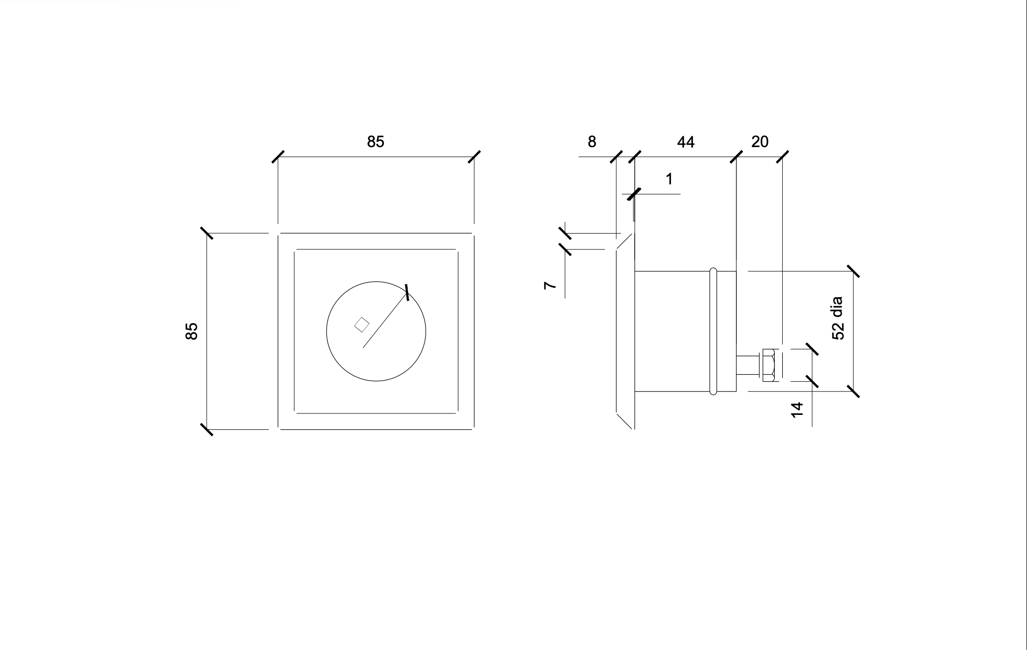
WT1.5-UWL
| CCT (K) | (5700K Cool White) (3000K Warm White) |
|---|---|
| CRI (Colour Rendering Index) | 85 |
| White Lumens | (900lm Cool) (750lm Warm) |
| White Wattage | 6W |
| Static Colour | Red 400lm Green 550lm Blue 350lm |
| RGB Wattage | 9W-3W per colour |
| RGB Lumens | Green 172lm Red 137lm Blue 162 Total 471lm |
| RGBW Lumens | Green 172lm Red 137lm Blue 162 Total 471lm White 200lm |
| Driver Requirements | 350mA Constant current MAX |
| Light Emitting area | 45mm Diameter |
| Lens Type | Flat, defused |
| Driver Control White & RGB | PWM |
| Face 316 stainless | 85mm |
| Body 316 stainless | 65mm |
| Fixing 2” Pipe | PN9 wall 2.5 I/D53mm |
| White Cable | 2 cores, 0.5mm2 wire size, 16/0.2mm (Blue Cathode) (Brown Anode) 6mm |
| RGB cable | 6-core 7-2-6a PVC insulation 6mm |
| RGBW cable | 8-core 7-2-6a PVC insulation 6mm |
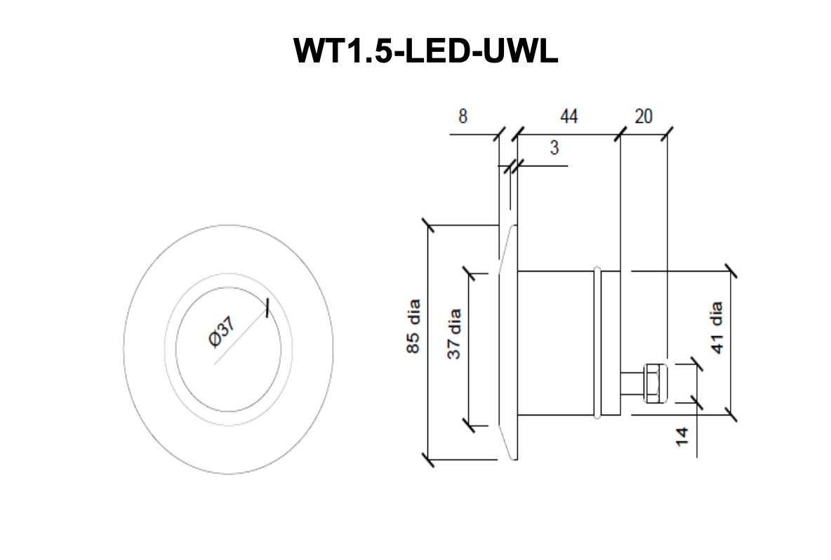
WT1.5-UWL
| CCT (K) | (5700K Cool White) (3000K Warm White) |
|---|---|
| CRI (Colour Rendering Index) | 85 |
| White Lumens | (900lm Cool) (750lm Warm) |
| White Wattage | 6W |
| Static Colour | Red 400lm Green 550lm Blue 350lm |
| RGB Wattage | 9W-3W per colour |
| RGB Lumens | Green 172lm Red 137lm Blue 162 Total 471lm |
| RGBW Lumens | Green 172lm Red 137lm Blue 162 Total 471lm White 200lm |
| Driver Requirements | 350mA Constant current MAX |
| Light Emitting area | 45mm Diameter |
| Lens Type | Flat, defused |
| Driver Control White & RGB | PWM |
| Face 316 stainless | 85mm |
| Body 316 stainless | 65mm |
| Fixing 2” Pipe | PN9 wall 2.5 I/D53mm |
| White Cable | 2 cores, 0.5mm2 wire size, 16/0.2mm (Blue Cathode) (Brown Anode) 6mm |
| RGB cable | 6-core 7-2-6a PVC insulation 6mm |
| RGBW cable | 8-core 7-2-6a PVC insulation 6mm |
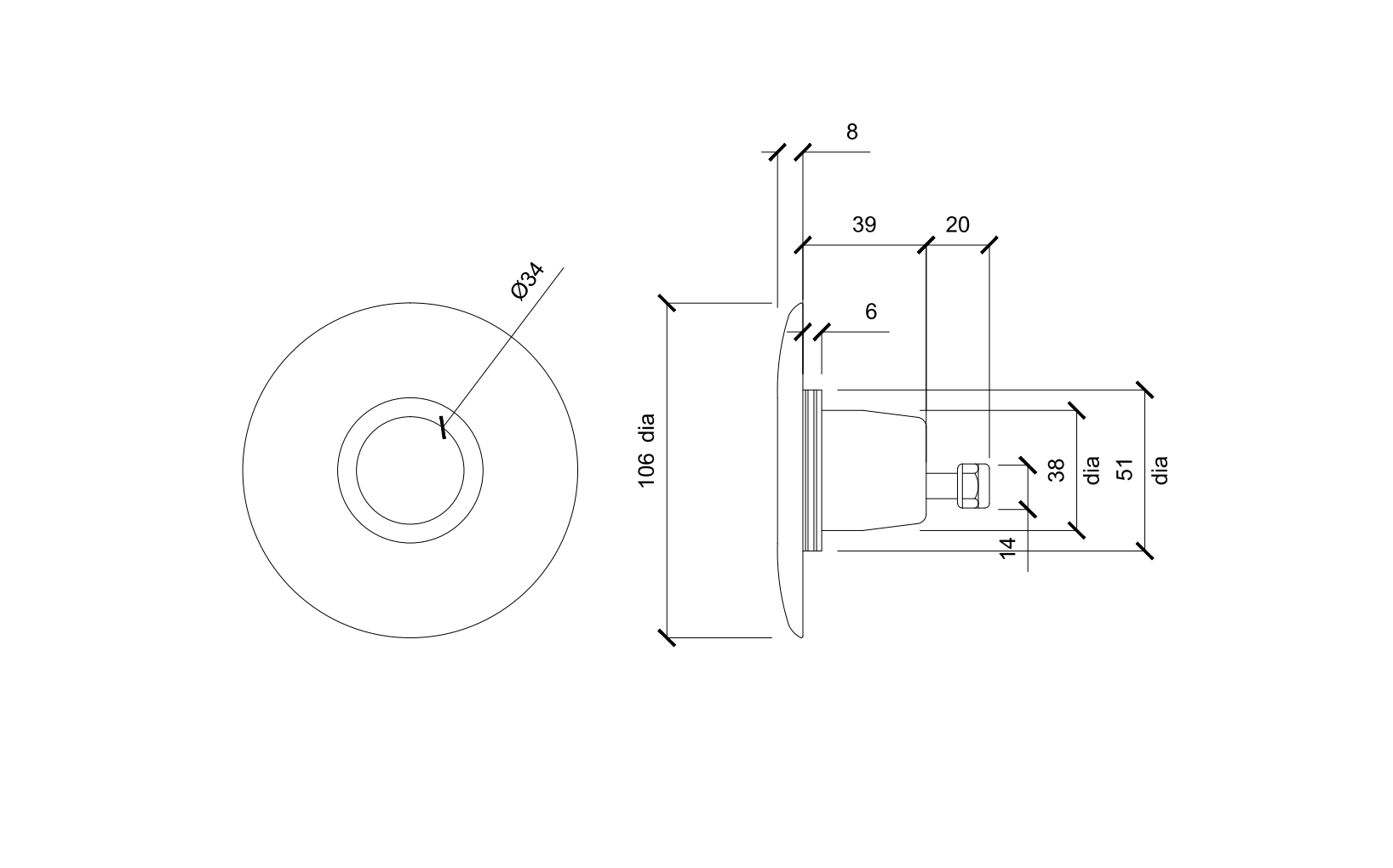
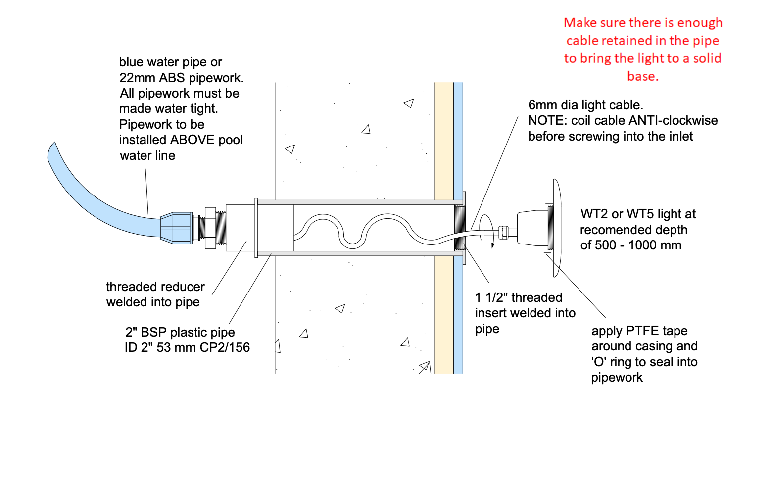
WT2-UWL
| CCT (K) | (5700K Cool White) (3000K Warm White) |
|---|---|
| CRI (Colour Rendering Index) | 85 |
| White Lumens | (900lm Cool) (750lm Warm) |
| White Wattage | 6W |
| Static Colour | Red 400lm Green 550lm Blue 350lm |
| RGB Wattage | 9W-3W per colour |
| RGB Lumens | Green 172lm Red 137lm Blue 162 Total 471lm |
| RGBW Lumens | Green 172lm Red 137lm Blue 162 Total 471lm White 200lm |
| Driver Requirements | 350mA Constant current MAX |
| Light Emitting area | 45mm Diameter |
| Lens Type | Flat, defused |
| Driver Control White & RGB | PWM |
| Face 316 stainless | 100mm Concrete 85m Liner |
| Body 316 stainless | 65mm |
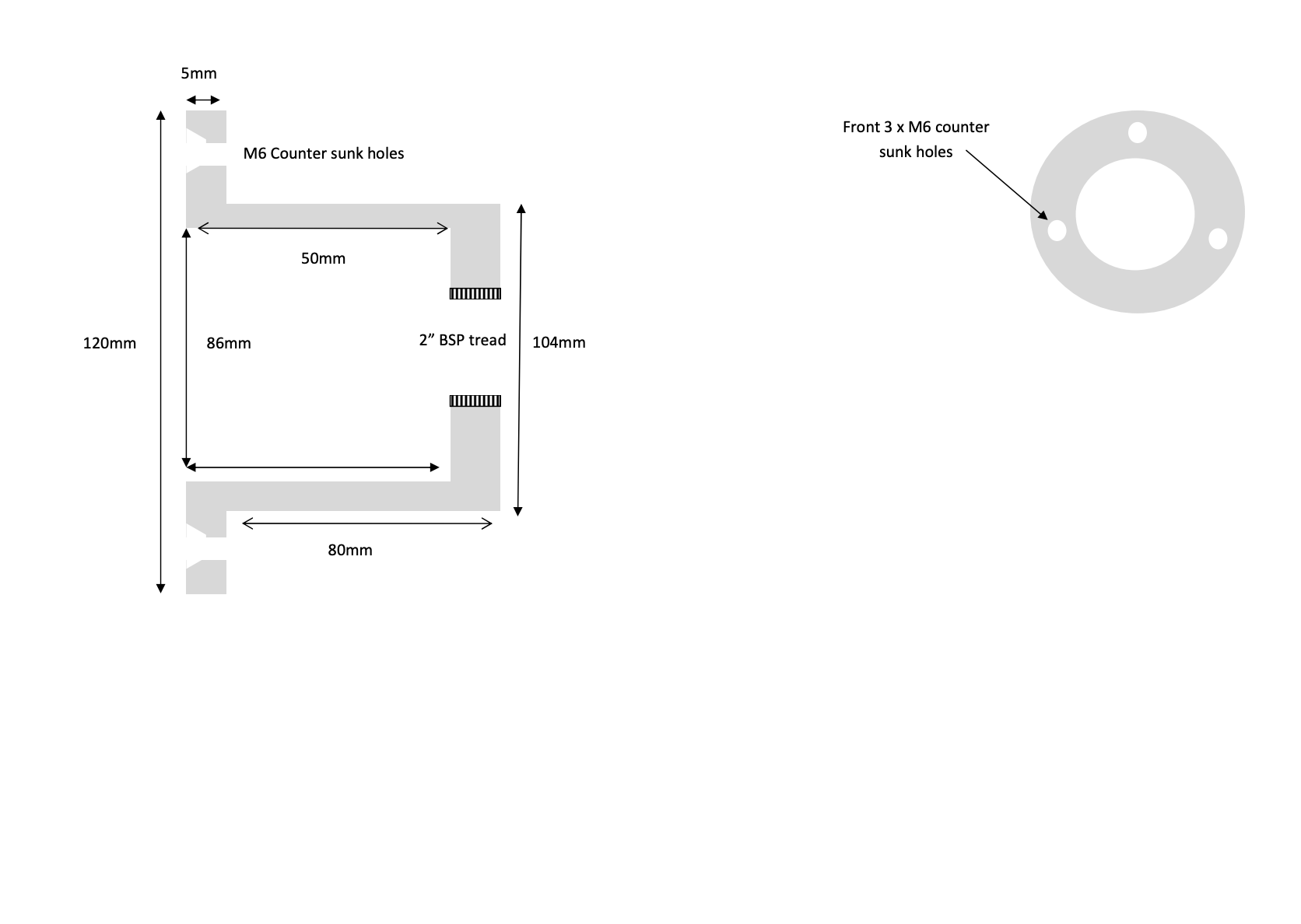
| Fixing 2” Pipe | 1.5 BSP Thread (inlet) |
| White Cable | 2 cores, 0.5mm2 wire size, 16/0.2mm (Blue Cathode) (Brown Anode) 6mm |
| RGB cable | 4-core 7-2-6a PVC insulation 6mm |
| RGBW cable | 5-core 7-2-6a PVC insulation 6mm |
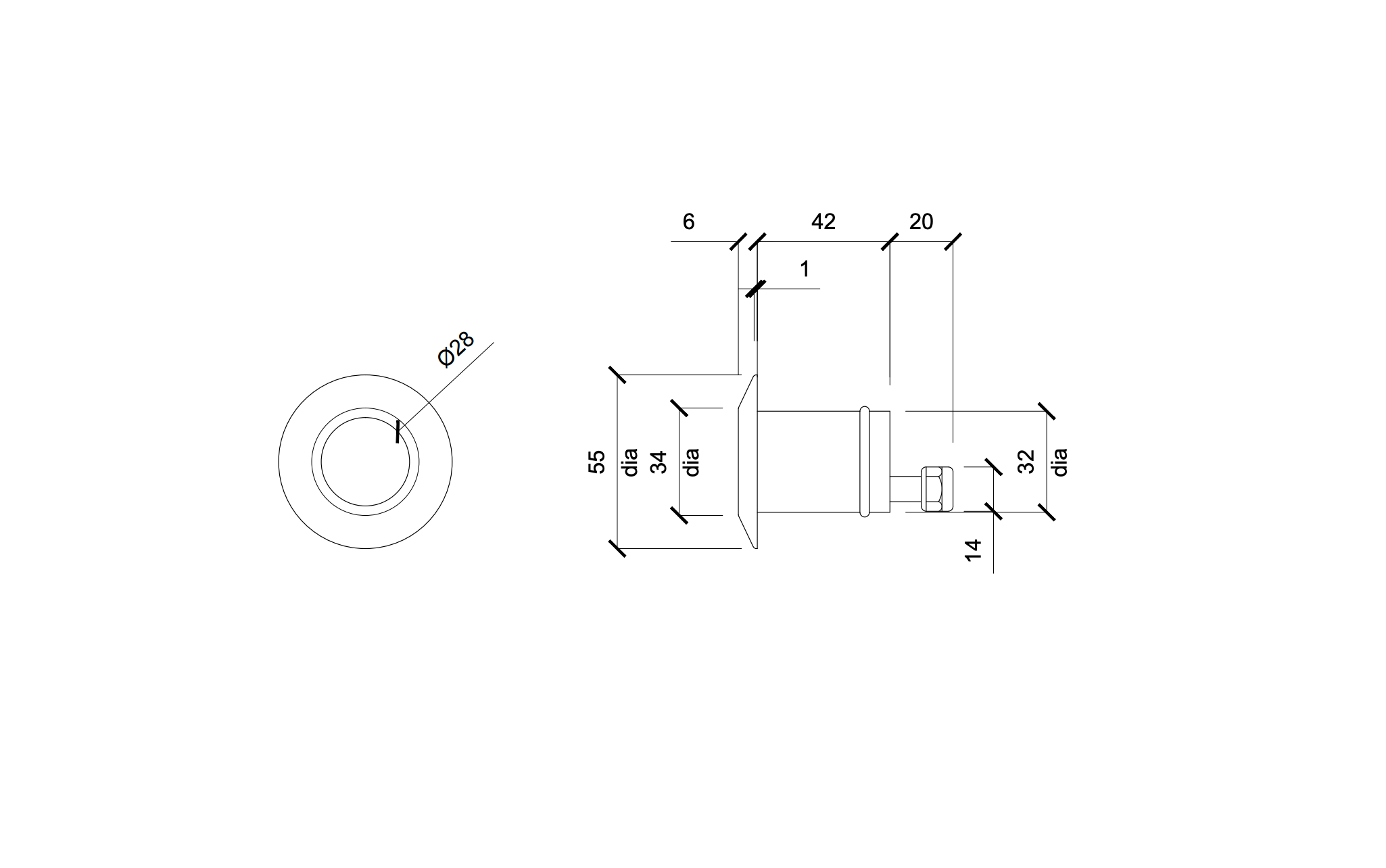
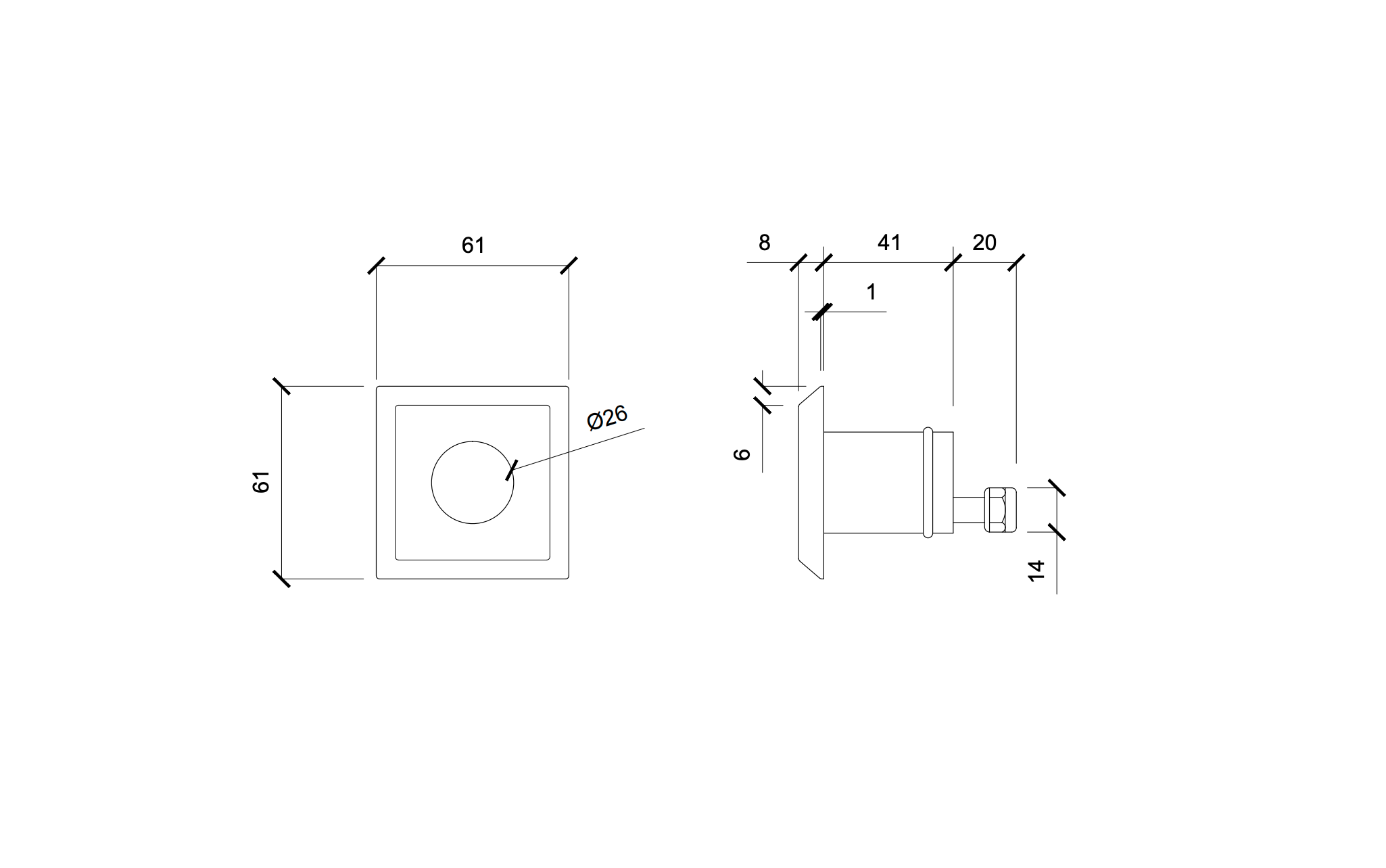
WT3-UWL
| CCT (K) | (5700K Cool White) (3000K Warm White) |
|---|---|
| CRI (Colour Rendering Index) | 85 |
| White Lumens | 300lm (Cool) (250lm Warm) |
| White Wattage | 2W |
| Static Colour | Red 150lm Green 175lm Blue 185lm |
| RGB Wattage | 9W-3W per colour |
| RGB Lumens | Green 72lm Red 37lm Blue 62 Total 471lm |
| Light Emitting area | 28mm Diameter |
| Lens Type | Flat, defused |
| Driver Control White & RGB | PWM |
| Face 316 stainless | 55mm Concrete 85m Liner |
| Body 316 stainless | 65mm |
| Fixing 2” Pipe | PN12 wall 2.2 I/D37mm |
| White Cable | 2 cores, 0.5mm2 wire size, 16/0.2mm (Blue Cathode) (Brown Anode) 6mm |
| RGB cable | 4-core 7-2-6a PVC insulation 6mm |
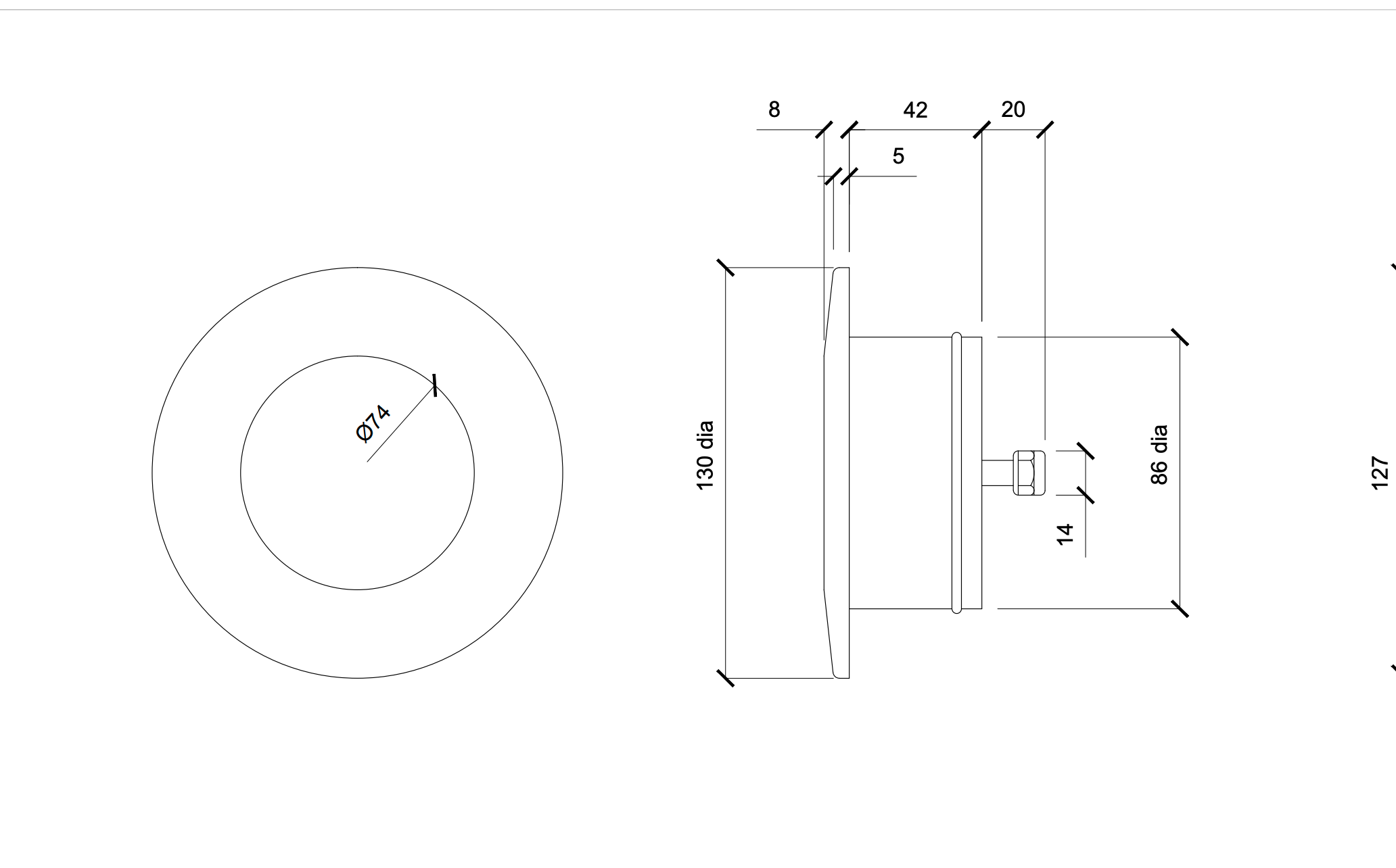
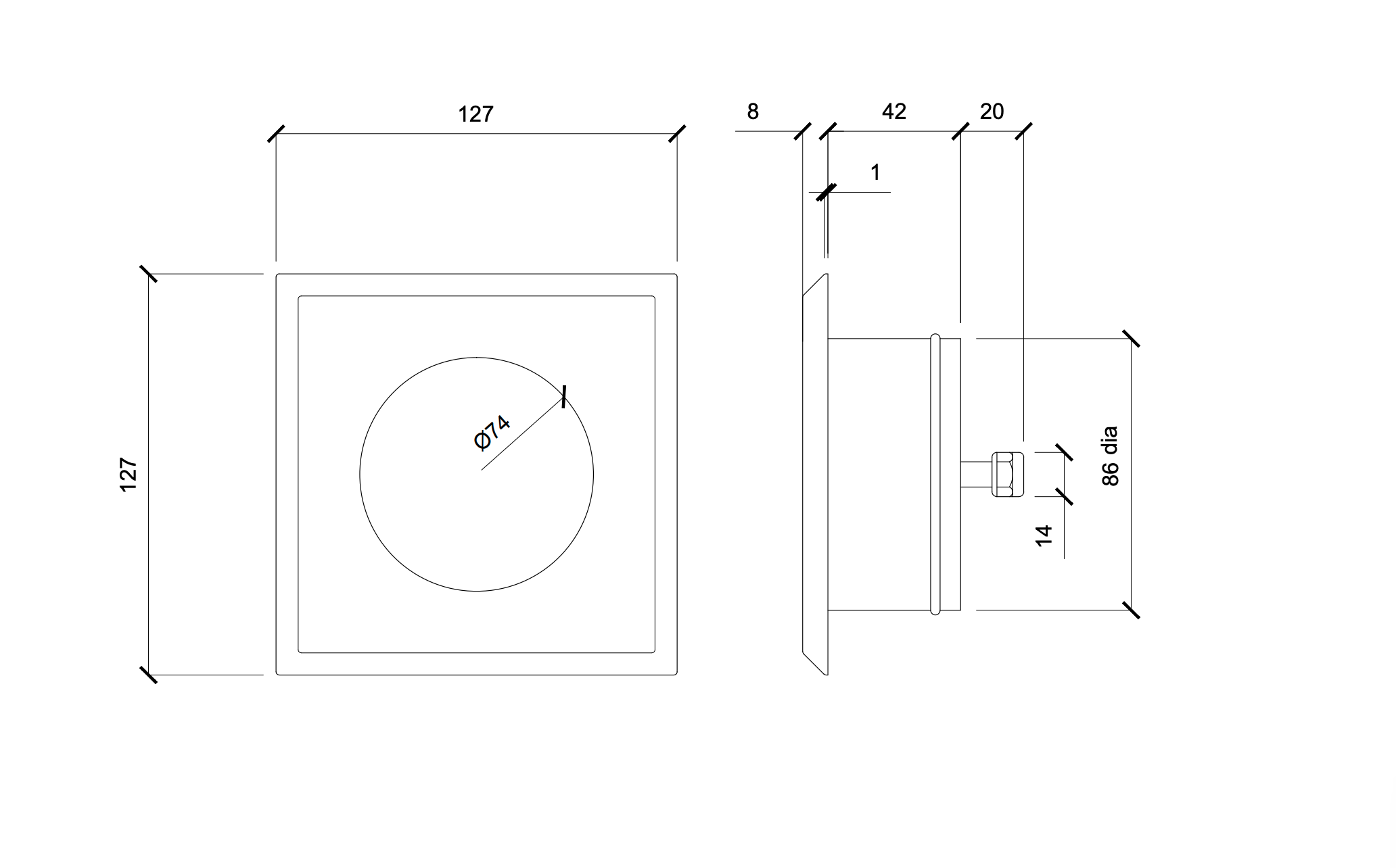
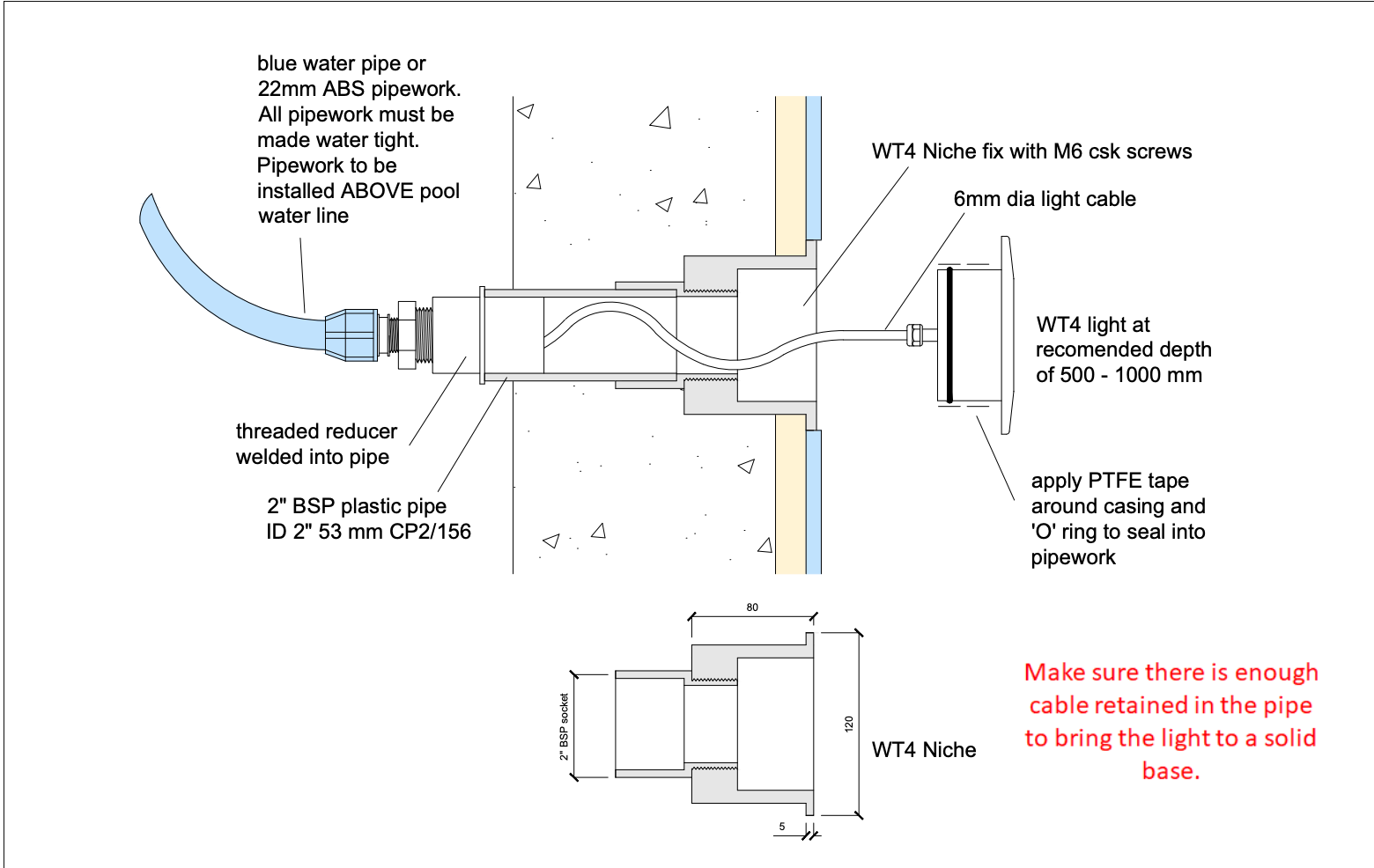
WT4-UWL
| CCT (K) | (5700K Cool White) (3000K Warm White) |
|---|---|
| CRI (Colour Rendering Index) | 85 |
| White Lumens | (2500lm Cool) (2000lm Warm) |
| White Wattage | 10W |
| Static Colour | Red 400lm Green 550lm Blue 350lm |
| RGB Wattage | 9W-3W per colour |
| RGB Lumens | Green 172lm Red 137lm Blue 162 Total 471lm |
| RGBW Lumens | Green 172lm Red 137lm Blue 162 Total 471lm White 200lm |
| Light Emitting area | 70mm Diameter |
| Lens Type | Flat, defused |
| Driver Control White & RGB | PWM |
| Face 316 stainless | 130mm |
| Body 316 stainless | 65mm |
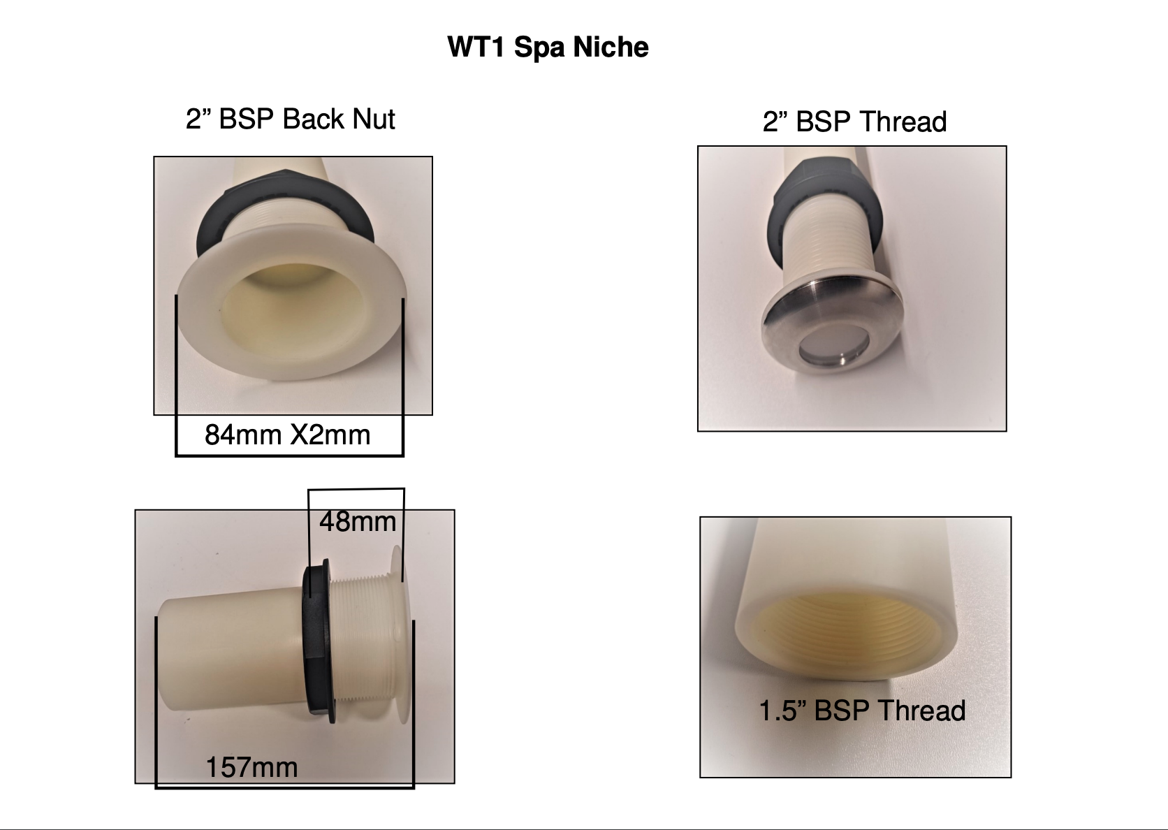
| Fixing 2” Pipe | WT Niche |
| White Cable | 2 cores, 0.5mm2 wire size, 16/0.2mm (Blue Cathode) (Brown Anode) 6mm |
| RGB cable | 4-core 7-2-6a PVC insulation 6mm |
| RGBW cable | 5-core 7-2-6a PVC insulation 6mm |
WT5-UWL
| CCT (K) | (5700K Cool White) (3000K Warm White) |
|---|---|
| CRI (Colour Rendering Index) | 85 |
| White Lumens | (1200lm Cool) (1000lm Warm) |
| White Wattage | 6W |
| Static Colour | Red 400lm Green 550lm Blue 350lm |
| RGB Wattage | 9W-3W per colour |
| RGB Lumens | Green 172lm Red 137lm Blue 162 Total 471lm |
| RGBW Lumens | Green 172lm Red 137lm Blue 162 Total 471lm White 200lm |
| Light Emitting area | 70mm Diameter |
| Lens Type | Fresnel Lens |
| Driver Control White & RGB | PWM |
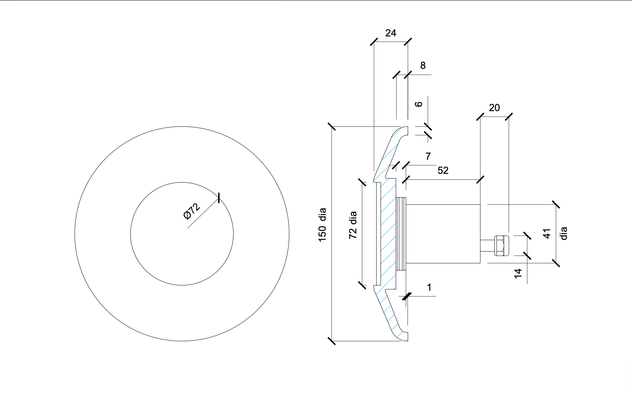
| Face 316 stainless | 150mm |
| Body 316 stainless | 65mm |
| Fixing 2” Pipe | 1.5 BSP Thread |
| White Cable | 2 cores, 0.5mm2 wire size, 16/0.2mm (Blue Cathode) (Brown Anode) 6mm |
| RGB cable | 4-core 7-2-6a PVC insulation 6mm |
| RGBW cable | 5-core 7-2-6a PVC insulation 6mm |
1 Introduction
This test work aimed to look at one aspect of the material changes for the lighting product, investigating the integrity of the newly introduced polymer seal material at the base of the screw thread in contact with the plastic face plate. The work aimed to look for signs of seal chemical compatibility issues with chemically shock treated model pool water to reduce the chance of future field failures. It is, however, not a comprehensive range of tests of all material combinations and corrosion issues, all possible rogue pool conditions or issues with assembly or maintenance during reassembly after replacement of the LED internal light sub- module.
The test plan was to analyse the internal seal to give a baseline for the materials prior to chemical exposure testing that will be used for comparison to determine if there had been any chemical or physical change to the material. Shore hardness measurements were used to look for hardening and embrittlement physical symptoms. FTIR was used to look for changes to the surface organic chemistry of the polymers and SEM/EDX looked for signs of physical attack like cracking and crazing that might compromise the water seal for example.
2 Sample Preparation/Method Details
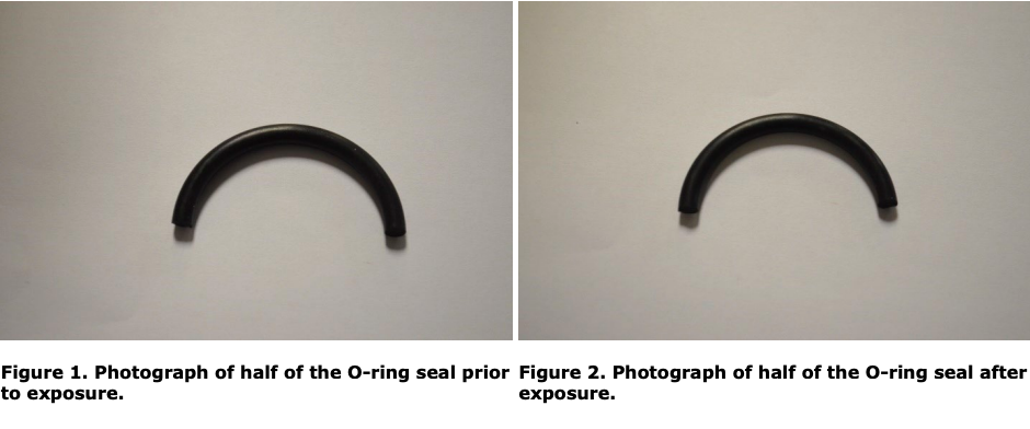
The Inner O-ring Seal from the LED light fitting was removed and cut in half with one half being exposed for 48 hours to the pool shock treatment and the other half being retained for comparison. See Figure 1 and Figure 2 for photographs of the seal before and after exposure.
A worst-case pool shock treatment was prepared containing approximately 30 ppm free chlorine (a normal shock treatment would be around 10 ppm) and approximately 40 ppm cyanuric acid. This was then pH adjusted to pH 7.2 using dilute hydrochloric acid.
It is important to distinguish between free chlorine and chloride as they are not the same. Chlorides form when ionic salts containing chloride ions (such as NaCl) dissociate in water. In the case of sodium chloride (NaCl) this leads to sodium ions and chloride ions surrounded by water molecules. This type of chemistry is typical in sea water.
In pool water, free chlorine is used at low levels in order to sanitise the pools and the chemistry is quite different to chloride chemistry. When a hypochlorite (such as calcium hypochlorite) is added to water it forms hypochlorous acid and a hydroxide ion, in this case calcium hydroxide.
Ca(OCl)2 + H2O 2 HOCl + 2 Ca(OH)2
One half of the O-ring seal was placed in a clean 100 mL beaker and covered in the accelerated pool shock treatment for 48 hours. The seal was then re-analysed after this treatment looking for any signs of physical or chemical degradation.
A Jasco FTIR-4100 with ATR accessory was used to obtain FTIR spectra for each of the samples.
Shore Hardness was measured on a Shore A Durometer, Model: TI-AC.
For SEM/EDX analysis samples were cut from the O-ring and seals and imaged under the optical microscope before being mounted onto SEM stubs and gold coated.
The use of gold as a coating creates a gold (Au) peak or peaks on the EDX spectra. This gold is part of the sample preparation and not part of the sample; therefore, this should be taken into account when interpreting the EDX data.
The optical microscopy was performed on a Leica MZ12 binocular microscope. The SEM and EDX analysis were performed on a Philips XL30 tungsten tip electron microscope with secondary electron and backscatter electron imaging detectors (SEM2). The beam energy used was 20keV which was high enough to include the majority of the elements in the periodic table, and low enough to minimise the electron probe sample volume. The EDX was performed on an EDAX UTW detector system.
The Optical Microscopy, SEM with EDX analysis were performed on the 25th February 2022.
The FTIR analysis and shore hardness measurements were performed on the 22nd and 25th February 2022.
The results relate to the sample as received and after suitable sample preparation for the technique used.
3 Results and Discussion
3.1 Shore A Hardness Results
Due to its size and shape the inner O-ring seal from the LED pool light was not ideal for taking Shore Hardness measurements, this led to slightly more variation in the results than would be typically seen.
Table 1 shows the results obtained for shore hardness for the inner O-ring seal both before and after exposure to the accelerated pool shock treatment.
While the values obtained varied slightly, it can be seen that there is no difference in the average hardness of the O-ring seal before and after exposure to the pool shock treatment.
Visual inspection of the O-ring seal did not show any change to its physical properties such as its elasticity or colour.
3.2 FTIR Results
Scans of the sample were taken prior to its exposure to the accelerated pool shock treatment on a Jasco FTIR-4100 using an ATR accessory.
In general, black samples lead to poor quality spectra since they absorb infrared light over a large range of frequencies. To try and offset this, a Germanium ATR crystal was used instead of the normal diamond ATR crystal. Using various settings spectra were obtained for the sample but the overall quality of the spectra was not as high as would normally be expected.
Figure 3 and Figure 4 show the FTIR spectra for the O-ring seal before and after exposure. There does not appear to be any significant differences between the FTIR spectra obtained for the O-ring seal before or after exposure to the pool treatment.
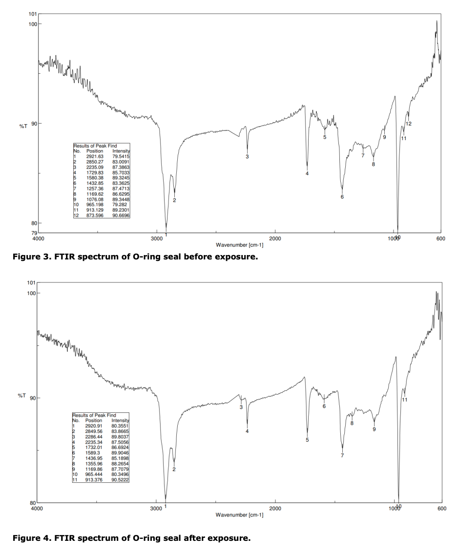
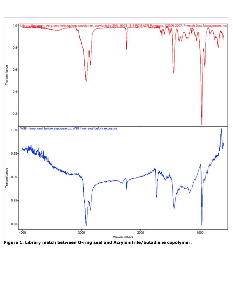
Figure 5 shows the library search obtained for the O-ring seal: This indicates that the seal is possibly an acrylonitrile / butadiene co-polymer with around a 67% match. It should be noted that the library is not a comprehensive list of all material types and manufacturer’s commercial products, so should only be treated as an indicative.
3.3 SEM/EDX Analysis
Optical microscopy, SEM and EDX analysis were used to look for any differences between the before and after exposure O-ring samples. More emphasis was placed on examining the surfaces of the components as this is where any damage would be more apparent. The bulk material of the O-ring was also examined by taking selected cross-sections of the O-ring.
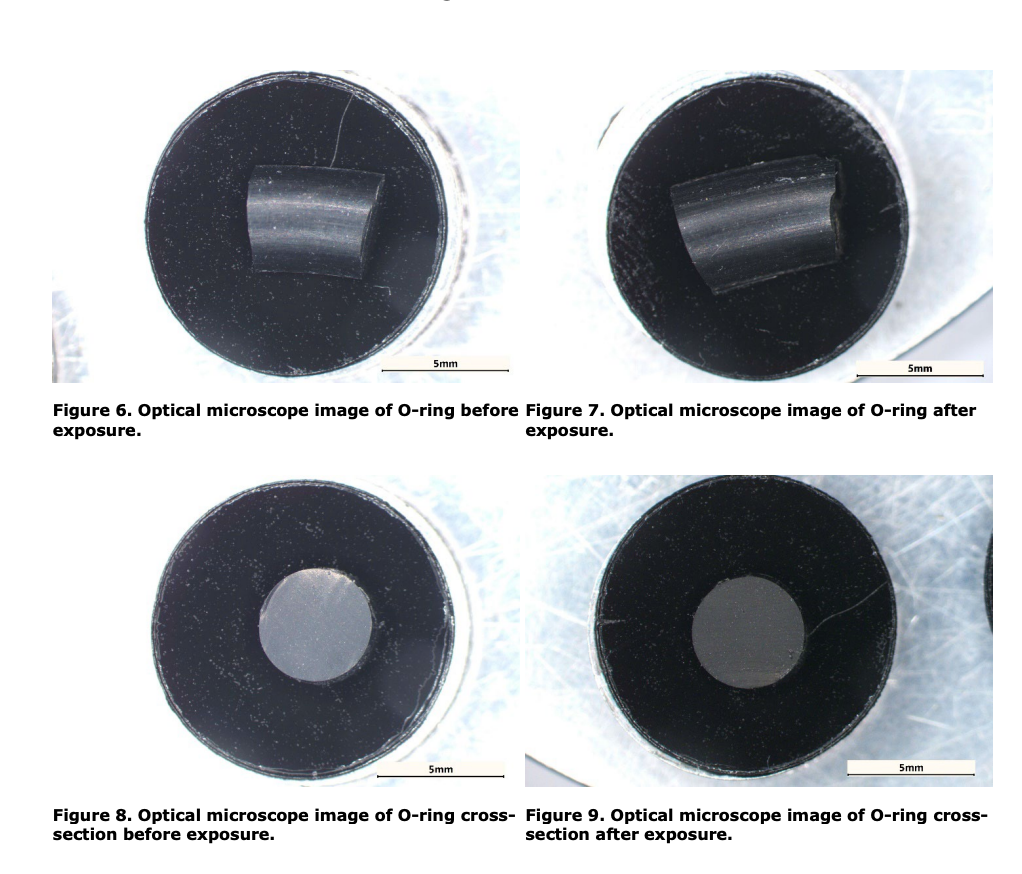
The components looked near-identical using the optical microscope in Figure 6 to Figure 9, so the samples were prepared for SEM/EDX analysis, looking at both the surfaces and the cross-sections of the O-ring.
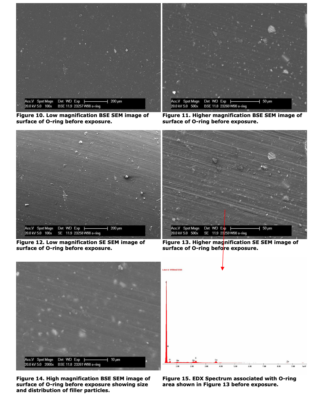
Both secondary electron imaging and backscatter imaging techniques were used to look at the surfaces of the components. Backscatter gives information on elemental composition based on contrast, i.e. the brighter the contrast, the heavier the element. Secondary electron imaging provides more topographical detail of the surfaces examined.
The O-ring had a slightly textured surface i.e. moulding striations are visible, and brighter contrasting filler particles can be observed in the Backscatter images.
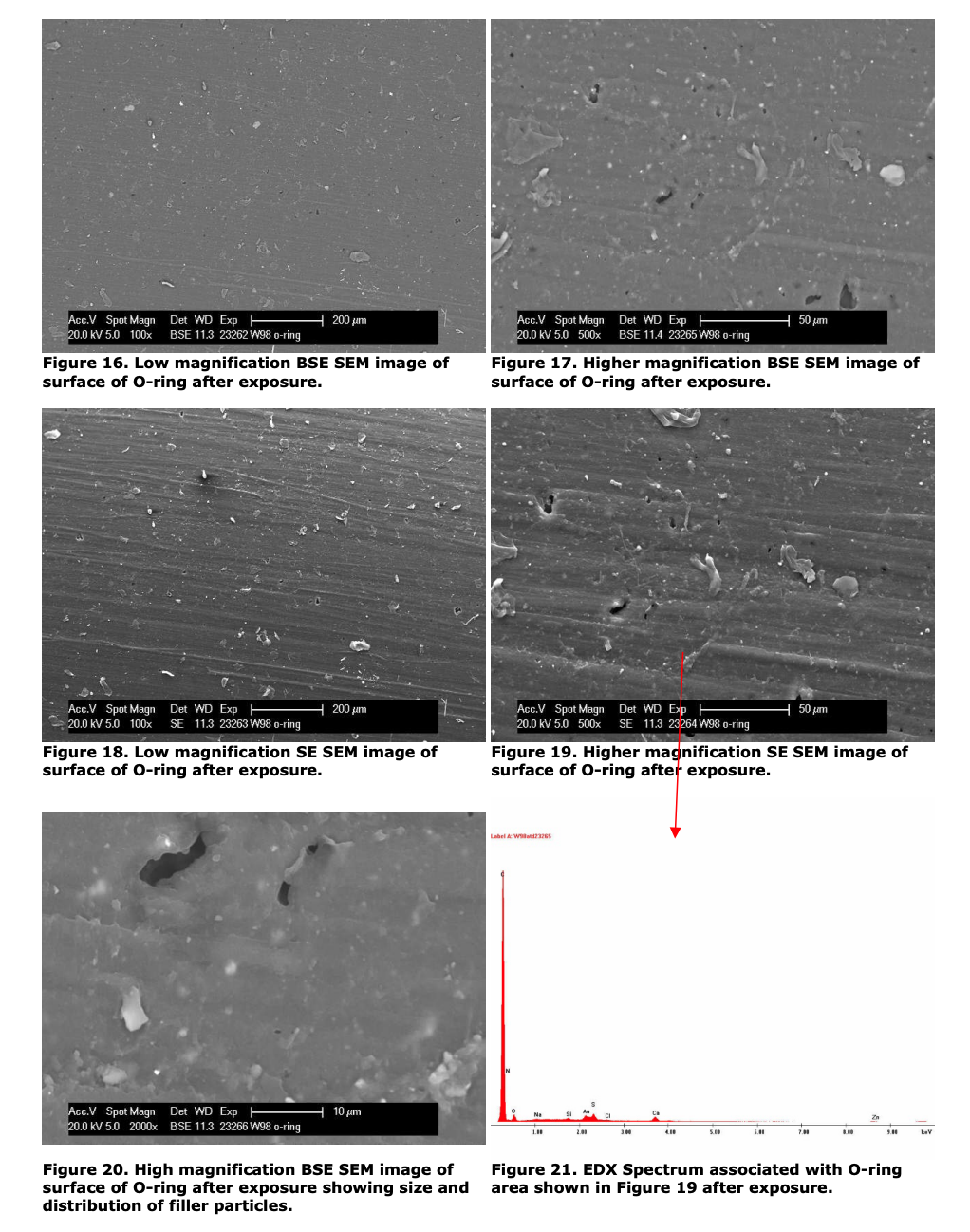
Comparing both low and high magnification images for the O-ring before and after exposure (Figure 10 and 11 compared with Figure 16 and 17), a slight difference in the surface of the O-ring after exposure was observed. Small holes were observed on the surface after exposure suggesting that the shock treatment may have removed some of the filler particles from the matrix. Removal of filler particles could potentially result in leaks over the lifetime of the seal. However, no cracking/crazing or swelling of the surface was observed. EDX analysis in Figure 15 and Figure 21 showed the elemental composition of the external surfaces of the O-rings before and after exposure were near-identical.
The EDX spectra show that the O-rings contain carbon, nitrogen, oxygen, sodium sulphur, calcium and zinc. This is in keeping with the FTIR findings as carbon, nitrogen and oxygen are consistent with acrylonitrile/butadiene. The calcium and sodium are likely to have originated from the filler materials and the zinc and sulphur are possible cross linking/curing agents used in the material.
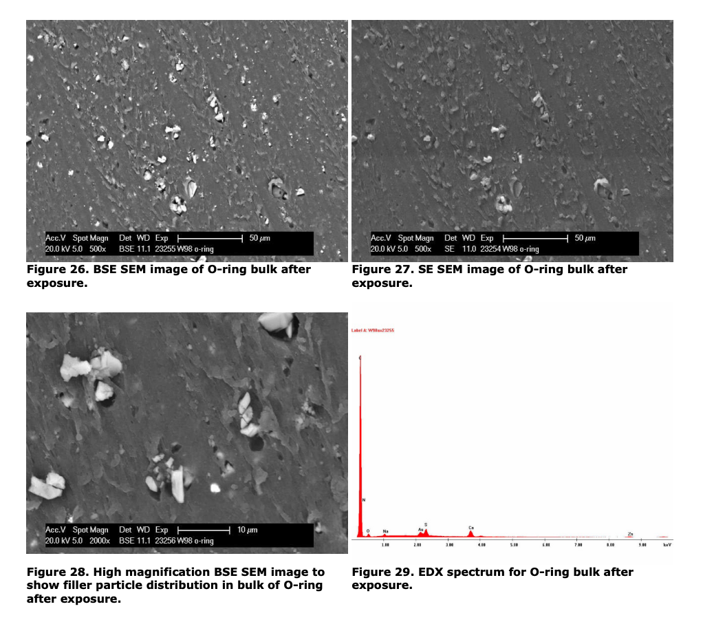
The bulk analysis was conducted on a freshly cut section of the material.
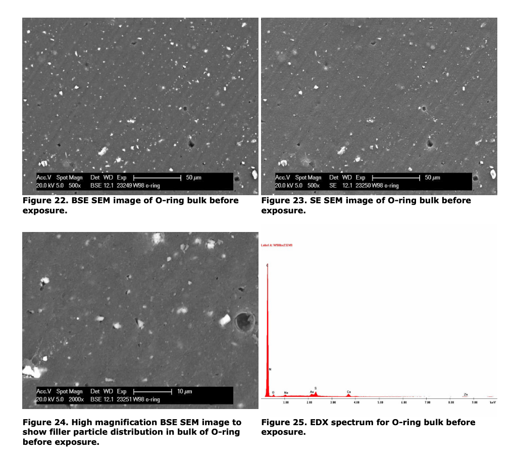
The bulk of the O-ring was examined to look for differences in elemental composition and filler material distribution after exposure to the pool shock treatment. No differences were found meaning that the shock treatment did not affect the bulk of the material which is logical since no effects of the shock treatment were observed in the surface analysis.
Small holes were observed on the cross-sections of the O-ring both before and after exposure. The holes on the cross sections are from removal of filler particles but this occurred as a consequence of sample preparation and should be ignored in this instance. When the sample was cut, the blade dislodged these filler particles.
4 Conclusions
FTIR and EDX analysis suggested that the accelerated pool shock treatment does not appear to have had any adverse effect on the chemical composition or structure of the O-ring, however, SEM analysis of the surface of the O-ring suggested that the pool shock treatment may have caused loss/dissolution of filler particles which could potentially result in leak paths being created.
Primary Author: Matthew Edwards & Dr Kim Nickson Function: Analytical Chemist & Senior Chemist / Lab Manager Signature: (hard copy only)________________
End of Report
Terms and conditions
Pool Care and maintenance.
You should avoid damage to the lamp by keeping the water at a neutral PH-value. Also the water should be free from metal attacking ingredients to avoid discolouration any material deposits on the lamp must be removed with a suitable non metallic cleaner.
The lamp must not come into contact with any metal effecting cleaners, or acids. Do not use high pressure cleaners directly onto the lamp.
Installation
The Installation of the lamp must be carried out according to the instructions supplied. If any modifications are made to the lamp, the manufacture is discharged from any liability. This includes modifications to the cables; they should not be cut or re-joined. The cables are supplied with the correct lengths specified. If any problems arise after installation by your chosen installer and it is found that the fault was of poor installation the manufacture is discharged from any liability.The Company accepts no responsibility for any direct or indirect damage as a result, of poor installation.
If the Buyer is overdue in payment for the goods or other goods supplied by the
Company, the Company may recover and sell the goods.
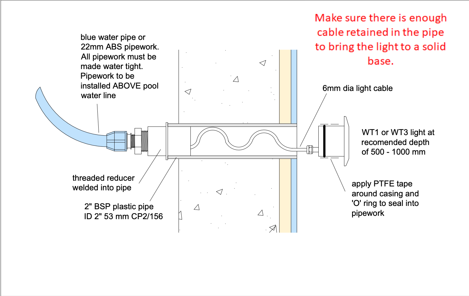
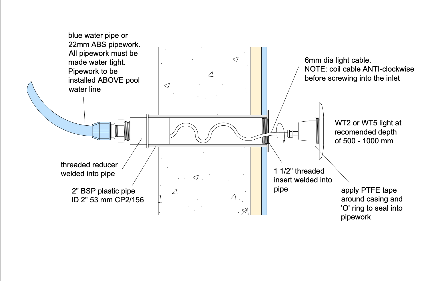
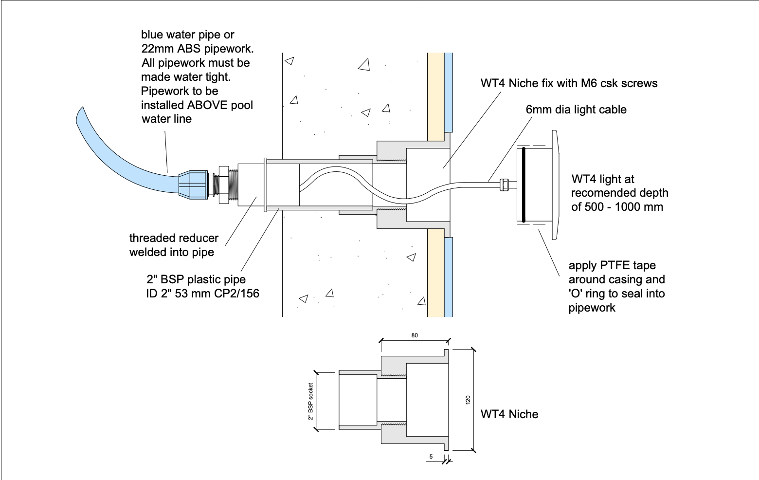
If you are not using the WT niche fitting, the manufactures is discharged from any liability. The lamp is equipped with cable lengths requested; the installer must ensure suitable draw wires are installed through the niche/pipe work and conduit.
General
The installation depth should be between 500mm to 700mm. Sufficient cable should be retained in the niche/pipe work to pull the lamp to the surface, and carry out any repairs. The lamps O ring is not a water tight seal therefore we recommend a soft sealant to be placed round the lip of the lamp prior to fitting.
If a lamp should fail then the replacement of an LED lamp should be carried out by a qualified electrician.
WARRANTY AND LIABILITY
(a) Subject to the conditions set out below, the Company warrants that the goods will be free from defects in material and workmanship for a period of 24 months from the date of delivery and shall replace any goods which the Buyer proves to the satisfaction of the Company to be faulty in accordance with this condition.
(b) The warranty given in paragraph (a) is subject to the following conditions.
(i) The Company shall be under no liability in respect of any defect arising from fair wear and tear, wilful damage, negligence, abnormal working conditions, poor installation, failure to follow the Company’s instructions, misuse or alteration or repair of the goods without the Company’s written approval.
(ii) The Company shall be under no liability under the above warranty if the total price for the goods has not been paid by the due date for payment.
(iii) The above warranty does not extend to parts, materials or equipment not
manufactured by the Company, in respect of which the Buyer shall only be entitled to
the benefit of any warranty or guarantee provided by the manufacturer thereof to the
Company.
(c) Subject as expressly provided in these conditions, all warranties, conditions or other terms implied by statute or common law are expressly excluded to the extent permitted by law.
(d) Except in respect of death or personal injury caused by the Company’s negligence (or implied under the Consumer Safety Act 1987) the Company shall not be liable to the Buyer by reason of any representation, implied warranty, condition or other term or under the express terms of the contract for any consequential loss or damage (whether for loss of profit or otherwise), costs, expenses or other claims for consequential compensation whatsoever arising out of the supply of goods and the Company’s liability for direct loss (otherwise than for death or personal injury) shall be limited to the value of the invoice for the contract.
WARRANTY AND LIABILITY
All our products are covered by your statutory rights, this warranty is in addition to your statutory rights under either the Sale of Goods Act 1979 or the Supply of Goods and Services Act 1982 .If you are unhappy with the service you receive from water-tec.co.uk please contact us immediately in order that we can rectify the situation. We will keep you informed of everything we are doing to correct the situation until the problem has been resolved. This warranty covers a 24 month period from the date of purchase. Conditions apply see below for details.
Warranty Disclaimer
This warranty takes immediate effect from the date of purchase.
- This warranty takes immediate effect from the date of purchase.
- Water-tec and MAS Electronics UK Ltd are not responsible for any items that have been damaged due to misuse.
- We are not responsible for the installation of the items; installation must always be carried out by a qualified electrician.
- General maintenance on the Lamps must be carried out at regular intervals, to ensure the highest visibility. We do not take responsibility for any maintenance issues.
- The water should be kept at a neutral Ph-value. The water should be free from any metal attacking ingredients to avoid discolouration.
- Material deposits on the lamp must be removed with a suitable non-metallic cleaner.
- Items returned and are found to be damage by any misuse or incorrect fitting; the manufactures are discharged from any liability. There will also be a charge to replace the item.
- This is a water-cooled device; therefore, the lamps should not be run dry for long periods of time.
- The warranty will be invalid if any modifications are made to the Lamps or cable.
- We do not recommend the water-tec lighting range within a salt pool.
- MAS Electronics UK Ltd does not cover consequential losses.